Categories
- Home
- About Us
- Technical Info
- Power Supply Connectors and Pinouts
Power Supply Connectors and Pinouts
- 12VHPWR MicroFit 3.0 Connectors
- ATX Power Housing Connectors Female
- ATX Power Housing Connectors Male
- Audio Speaker Headphone Connectors
- Aviation Plug GX16
- Connector Terminal Pins
- D Sub DB9 DB15 DB25 Connectors
- DC AC Power Socket Plug Connectors
- Dupont Internal Header Connectors
- EMI RFI Components
- Fan Connectors
- Floppy Connectors
- HDMI DVI Connectors
- IDC Connectors
- Lighting and RGB Connectors
- M.2 NVMe NGFF SSD Connectors
- PCIE PCI AGP Slots
- PSU Modular Connector Sets
- Molex Connectors 4 Pin
- RJ45 RJ11 K1 RS232 Connectors
- SATA Connectors
- Switches
- USB Connectors
12VHPWR 12V-2X6 Connector Specifications and Pinout
The 12VHPWR (12V-2x6) connector is a 16‑pin PCIe power standard designed to deliver up to 600 W to modern GPUs, with enhanced safety features in its revised 12V‑2x6 form that ensure proper seating of power and sense pins. It uses twelve power pins and four sense pins, supports up to 9.5 A per contact, and is backward compatible with earlier 12VHPWR cables.
- Pinout & Layout
- Total pins: 16 (12 power + 4 sense/signal)
- Arrangement: Two parallel rows of six power pins, plus four smaller sense pins above.
- Pitch: Power pins at 3.0 mm spacing (tighter than legacy 6‑pin/8‑pin PCIe connectors at 4.2 mm).
- Sense pins: Communicate allowable power draw (150 W, 300 W, 450 W, or 600 W depending on configuration). In the 12V‑2x6 revision, sense pins are shorter to prevent GPU startup unless the connector is fully seated.
- Electrical Specifications
- Voltage rating: 12 V DC
- Current rating: Up to 9.5 A per power pin (with all 12 pins energized)
- Signal pins: Rated at 1 A each
- Total power capacity: Up to 600 W continuous delivery
- Contact resistance: ≤ 5 mΩ (power), ≤ 10 mΩ (sense)
- Dielectric withstand voltage: 2200 V AC
- Insulation resistance: ≥ 1000 MΩ
- Mechanical & Safety Features
- Insertion force: 4–8 N depending on terminal type
- Withdrawal force: 0.6–2.4 N minimum retention
- Durability: 50 mating cycles
- Housing material: UL 94 V‑0 flame‑retardant nylon or LCP (black)
- Contacts: High‑conductivity copper alloy, tin/gold plated
- Cable gauge: Typically, 16 AWG for PSU leads
- Revision improvements (12V‑2x6)
- Power pins extended by 0.15 mm for better contact area
- Sense pins shortened by 0.1 mm to enforce full seating before power negotiation
- Housing latch tolerance adjusted for tighter fit
- Marked “H++” instead of “H+”
- Backward Compatibility
- 12V‑2x6 connectors are backward compatible with existing 12VHPWR cables.
- GPUs like the Nvidia RTX 4070 already ship with the new 12V‑2x6 connector, but users can still use older 12VHPWR cables safely.
- Risks & Considerations
- Partial insertion has historically caused overheating and melting issues. The 12V‑2x6 revision mitigates this by requiring full seating before sense pins engage.
- Cable quality matters: Use certified 16 AWG cables with proper crimps and shielding.
- Adapters: Multi‑8‑pin to 16‑pin adapters exist but can introduce additional resistance and risk if poorly made.
In summary, the 12VHPWR / 12V‑2x6 connector is the modern PCIe GPU power standard, engineered for 600 W delivery, 9.5 A per pin, and safer insertion mechanics. For system builders, ensuring proper seating, certified cables, and PSU compliance with ATX 3.0/3.1 is critical to avoid failures.


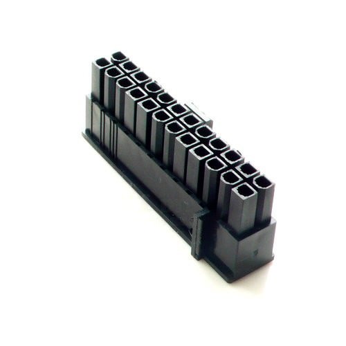
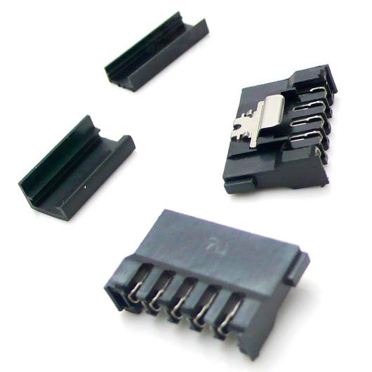
Standard 4.2mm Pitch ATX Header Connector Datasheet
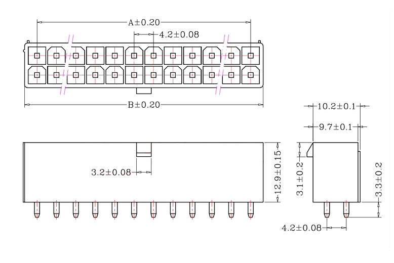
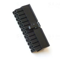
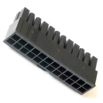
ATX 24 Pin Main Power Cable Connector
The 24 pin main power connector was added in ATX12V 2.0 to provide extra power needed by PCI Express slots. The older 20 pin main power cable only has one 12 volt line. The new 24 pin connector added one line apiece for ground, 3.3, 5, and 12 volts. The extra pins made the auxiliary power cable unnecessary so most ATX12V 2.x power supplies don't have them. The 24 pin connector is polarized so it can only be plugged in pointing in the correct direction.
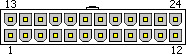
| Pinout | |||||
|---|---|---|---|---|---|
| Pins 1 through 12 | Pins 13 through 24 | ||||
| Description | Wire color | Pin number | Pin number | Wire color | Description |
| +3.3 volts | orange | 1 | 13 | orange | +3.3 volts |
| +3.3 volts | orange | 2 | 14 | blue | -12 volts |
| ground | black | 3 | 15 | black | ground |
| +5 volts | red | 4 | 16 | green | PS_ON# |
| ground | black | 5 | 17 | black | ground |
| +5 volts | red | 6 | 18 | black | ground |
| ground | black | 7 | 19 | black | ground |
| PWR_OK | gray | 8 | 20 | white | -5 volts (optional) |
| VSB +5 volts | purple | 9 | 21 | red | +5 volts |
| +12 volts | yellow | 10 | 22 | red | +5 volts |
| +12 volts | yellow | 11 | 23 | red | +5 volts |
| +3.3 volts | orange | 12 | 24 | black | ground |
Some of the voltage lines on the connector may have smaller sense wires which allow the power supply to sense what voltage is actually seen by the motherboard. These are pretty common on the 3.3 volt line in pin 13 but are sometimes used for other voltages too. The -5 volt line on pin 20 was made optional in ATX12V 1.3 (introduced in 2003) because -5 had been rarely used for years. Newer motherboards virtually never require -5 volts but many older motherboards do. Most newer power supplies don't provide -5 volts in which case the white wire is missing.
| Connector part numbers | |||
|---|---|---|---|
| Motherboard connector | Cable connector | Terminals | Maximum current per circuit |
| Molex 39-28-1243 | Molex 39-01-2240 | Molex 39-00-0168, Molex 44476-1111 |
6 amps |
| Unofficial cable/connector maximum wattage delivery for main rails | |||
|---|---|---|---|
| Voltage rail | Number of lines | Maximum current | Maximum wattage |
| +3.3 volts | 4 | 24 amps | 79.2 watts |
| +5 volts | 5 | 30 amps | 150 watts |
| +12 volts | 2 | 12 amps | 144 watts |
If you have an ATX power supply with a 24 pin main cable, it's okay to plug it into a motherboard with a 20 pin connector. It was designed to work that way. You can see an example in the picture above. The extra 4 pins on the cable just hang over the end of the motherboard connector. The 24 pin cable only fits into a 20 pin socket at one end so you can't plug it in incorrectly. The extra 4 pins were added to the 24 pin version of the cable to provide one extra wire for ground, 3.3, 5, and 12 volts. But it's okay to leave those 4 pins disconnected because a motherboard with a 20 pin connector doesn't need them. The only problem you can bump into (literally) is if there is something blocking the spot where the 24 pin cable hangs over the end. Or sometimes the end of the 20 pin motherboard connector is too thick to fit between the pins of the 24 pin cable. You can solve that problem by carefully shaving down one end of the 20 pin motherboard connector. It's just plastic. You won't miss it. If you can't get them to fit together then you can get an adapter cable which will make it work. The 24 pin cable plugs into one end of the adapter and then the adapter plugs into the 20 pin motherboard. But you should avoid using that kind of adapter if you can because the extra wire and connector are just more things which can go wrong. Adapters also slightly increase the voltage drop which is something worth avoiding. It's better to first see if you can get a 24 pin cable to fit into a 20 pin motherboard before resorting to an adapter.
ATX 20+4 Pin Main Power Cable Connector

Motherboards can come with either a 20 pin main power connector or a 24 pin main power connector. Many power supplies come with a 20+4 cable which is compatible with both 20 and 24 pin motherboards. A 20+4 power cable has two pieces: a 20 pin piece, and a 4 pin piece. If you leave the two pieces separate then you can plug the 20 pin piece into a 20 pin motherboard and leave the 4 pin piece unplugged. Be sure to leave the 4 pin piece unplugged even if it fits into another connector. The 4 pin piece is not compatible with any other connectors. If you plug the two pieces of a 20+4 power cable together then you have a 24 pin power cable which can be plugged into a 24 pin motherboard.
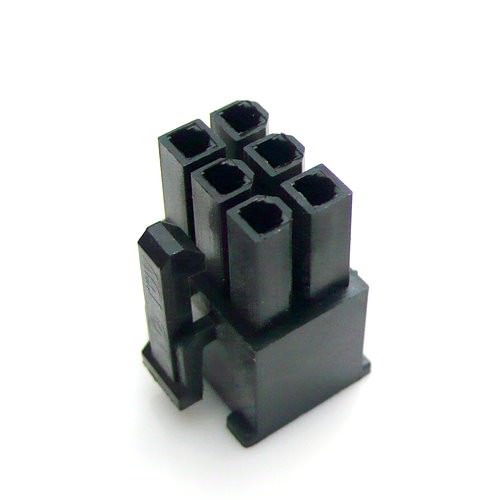
8 Pin EPS +12 Volt Power Cable Connector
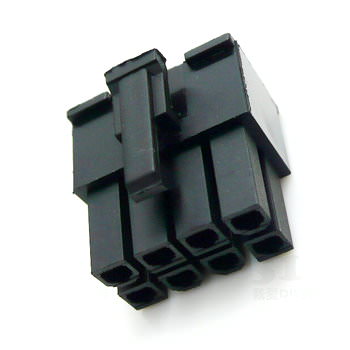
This cable was originally created for workstations to provide 12 volts to power multiple CPUs. But as time has passed many CPUs require more 12 volt power and the 8 pin 12 volt cable is often used instead of a 4 pin 12 volt cable. Depending on the power supply, the connector may contain one 12 volt rail in all 8 pins or two 12 volt rails taking up 4 pins apiece. It is often refered to as an "EPS12V" cable.
The 8 pin 12 volt cable is polarized so it can only be plugged into the 8 pin motherboard connector correctly. If you look carefully at the picture above you can see that four of the pins are square and the other four have rounded corners. The motherboard connectors also have the same square and rounded arrangement so the power cable only fits in one way. At least that's true unless you try really hard to force it into the connector. With enough force you can sometimes get a cable with a small number of pins into a connector which doesn't match. The 8 pin cable has enough pins that it's pretty hard to insert it in the wrong direction but determined people might be able to do it. If you look carefully you can also see that the square and rounded pattern matches various positions on other motherboard connectors like the 20 pin main power connector and 24 pin main power connector. You should only plug the 8 pin 12 volt cable into the motherboard connector where it belongs unless you enjoy the smell of fried electronics.
You can also plug an 8 pin 12 volt cable into a 4 pin 12 volt motherboard connector. I don't have a picture of this one but it looks similar to this. Four of the pins on the 8 pin cable fit into the motherboard connector and the other four pins hang off the end. The 8 pin cable only fits into one end of the 4 pin motherboard connector unless you try hard to force it into the wrong position. The 8 pin cable is electrically compatible but it may not fit into a 4 pin motherboard. There is often a component which blocks the area where the 4 pins would hang off the end. And sometimes the plastic end of the 4 pin connector is too thick to fit between the pins of the 8 pin cable.
Make sure that you don't try to plug an 8 pin 12 volt cable into the 8 Pin PCI Express power connector on a video card. The two cables look very similar so it's easy to get the two confused. 8 Pin PCI Express power cables are usually labeled to distinguish them from 8 pin 12 volt cables. The PCI Express cable usually has "PCI-E" printed on the connector. If there are no labels then you can usually use wire colors to tell the two kinds of cables apart. An 8 pin 12 volt cable has yellow wires on the same side as the connector clip. An 8 Pin PCI Express cable has black wires on the clip side. The two power cables are also keyed differently so you can't plug one kind of power cable into the other kind of connector. But as with this kind of connector, you can sometimes force the wrong kind of cable into a connector if you push hard enough. Make sure you have the right kind of cable before plugging it in. The two are definitely not compatible with each other.
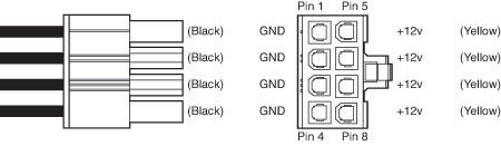
| Pinout | |||||
|---|---|---|---|---|---|
| Pins 1 through 4 | Pins 5 through 8 | ||||
| Description | Wire color | Pin number | Pin number | Wire color | Description |
| ground | black | 1 | 5 | yellow | +12 volts (12V1) |
| ground | black | 2 | 6 | yellow | +12 volts (12V1) |
| ground | black | 3 | 7 | yellow | +12 volts (12V1 or 12V2) |
| ground | black | 4 | 8 | yellow | +12 volts (12V1 or 12V2) |
| Connector part numbers | |||
|---|---|---|---|
| Motherboard connector | Cable connector | Terminals | Maximum current per circuit |
| Molex 39-28-1083 | Molex 39-01-2080 | Molex 39-00-0168, Molex 44476-1111 |
7 amps |
| Unofficial cable/connector maximum wattage delivery | |||
|---|---|---|---|
| Voltage rail | Number of lines | Maximum current | Maximum wattage |
| +12 volts | 4 | 28 amps | 336 watts |
If you don't have an 8 pin 12 volt cable then you can use the adapter shown above. It converts a couple of 4 pin peripheral power cables into an 8 pin 12 volt cable. If you use one of these adapters then be sure to plug the 4 pin peripheral connectors into separate cables coming from the power supply. If you plug them both into the same power supply cable then you are drawing all the power of the 8 pin 12 volt connector through a single 18 gauge wire. You can often get away with that but there's no reason to do it.
4+4 Pin +12 Volt Power Cable Connector
Motherboards can come with either a 4 pin 12 volt connector or an 8 pin 12 volt connector. Many power supplies come with a 4+4 pin 12 volt cable which is compatible with both 4 and 8 pin motherboards. A 4+4 power cable has two separate 4 pin pieces. If you plug the two pieces of a 4+4 power cable together then you have a 8 pin power cable which can be plugged into an 8 pin 12 volt connector. If you leave the two pieces separate then you can plug one of the 4 pin pieces into a 4 pin 12 volt connector and leave the other 4 pin piece unplugged.
If you look carefully at the image above then you can see the polarization of the pins which prevents you from plugging the cable in improperly. Some of the pins are square and some of them have rounded off corners. The motherboard connectors have matching square and rounded off corners to prevent the cable from being plugged in the wrong way. But if you look really carefully at the right half of this particular cable and then look at the 8 pin 12 volt cable pictured above you'll notice that they don't match. A regular 8 pin cable has four square pins and four rounded ones but the 4+4 cable shown above has two square pins and 6 rounded ones. The left half of the 4+4 matches the left half of an 8 pin cable but the right half is different. Hmmmm... And this isn't some bizarre cable either. I've seen plenty of 4+4s which look like this one. And then there are other 4+4 cables which look just like an 8 pin cable split in two (which makes sense). Since rounded pins fit into square holes in motherboard connectors, this particular cable will fit just fine into an 8 pin 12 volt motherboard connector. But both halves of this 4+4 will fit into a 4 pin 12 volt motherboard connector. You're supposed to use the left half of the cable shown above when plugging it into a 4 pin motherboard connector but the right half will also fit. As it happens, either half will work fine in a 4 pin motherboard because both halves of the 4+4 just provide 12 volts. The pinouts are the same for both halves so either one will work. I'm not sure why they make cables like this one because you'd figure a 4+4 cable would just be an 8 pin cable which splits in two. And you only need one half of a 4+4 cable to plug into a 4 pin motherboard. The other half is unused. But the kind of 4+4 cable shown above is pretty common so don't let it throw you.
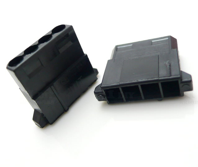
6 Pin PCI Express (PCIe) Power Cable Connector

This cable is used to provide extra 12 volt power to PCI Express expansion cards. PCI Express motherboard slots can provide a maximum of 75 watts. Many video cards draw significantly more than 75 watts so the 6 pin PCI Express power cable was created. These high-power cards draw most of their power from the 12 volt rail so this cable provides only 12 volts. These are sometimes called "PCI Express cables". They are also occasionally called "PEG cables" where "PEG" stands for PCI Express Graphics. If your power supply doesn't have a 6 pin PCI Express cable then you can use the adapter shown above on the right to convert two 4 pin peripheral cables into a PCI Express cable. If you use an adapter then be sure to plug the 4 pin peripheral connectors into separate cables coming from the power supply. If you plug them both into the same power supply cable then you are drawing all the power of the PCI Express connector through a single 18 gauge wire. You can usually get away with that but there's no reason to do it. The PCI Express 6 pin connector is polarized so it can only be plugged in pointing in the correct direction. But as with connectors of this type, you can sometimes force them into the wrong kind of socket if you try hard enough. If it doesn't slide in easily then you're probably plugging it into the wrong place.
Some video cards come with the 8 pin PCI Express power connector to support higher wattage than the 6 pin PCI Express connectors. It's okay to plug a 6 pin PCI Express power cable into an 8 pin PCI Express connector. It's designed to work that way but will be limited to the lower wattage provided by the 6 pin version of the cable. The 6 pin cable only fits into one end of the 8 pin connector so you can't insert it incorrectly but you can sometimes force the 6 pin cable in the wrong way if you try hard enough. Video cards can sense whether you have plugged a 6 pin or 8 pin cable into an 8 pin connector so the video card can impose some kind of restriction when running with only a 6 pin power cable. Some cards will refuse to run with only a 6 pin cable in an 8 pin socket. Others will work with a 6 pin cable at normal speeds but will not allow overclocking. Check the video card documentation to get the rules. But if you don't have any other information then just assume that if your video card has an 8 pin connector then you must plug in an 8 pin cable.
| Pinout | |||||
|---|---|---|---|---|---|
| Pins 1 through 3 | Pins 4 through 6 | ||||
| Description | Wire color | Pin number | Pin number | Wire color | Description |
| +12 volts | yellow | 1 | 4 | black | ground |
| +12 volts or not connected | yellow or not connected | 2 | 5 | black | ground |
| +12 volts | yellow | 3 | 6 | black | ground |
| Connector part numbers | |||
|---|---|---|---|
| Video card connector | Cable connector | Terminals | Maximum current per circuit |
| Molex 45558-0002 | Molex 45559-0002 | Molex 39-00-0168, Molex 44476-1111 |
8 amps |
| Official cable/connector maximum wattage delivery | |||
|---|---|---|---|
| Voltage rail | Number of lines | Maximum current | Maximum wattage |
| +12 volts | 3 | 2.083 amps | 75 watts |
The PCI Express specification is, unfortunately, not a free, public specification. So most people have never seen it. Including me. ATX specification: freely available to all. PCI Express specification: expensive so hardly anyone has seen it. ATX: good. PCI Express: bad. It's a shame when a widely used standard isn't freely available to the public. Nonetheless, information leaks out from the specification and the 6 pin PCI Express power cable is actually rated at an extremely conservative 75 watts. I have no idea why the wattage is rated so low because the specifications from Molex clearly allow substantially more power. Part of the reason may be that pin 2 (listed above as a 12 volt line) may be listed as not connected in the specification. I've never seen a 6 pin PCI Express power cable with pin 2 not connected. They've all had a 12 volt line connected to pin 2. I've also seen claims that there may be unimplemented sense lines in the specification. Welcome to the uncertainty which happens when you don't have freely available specifications. Even with only two 12 volt lines the standard implementation of PCI Express power cables use large enough gauge wire and a good enough connector to provide much more than the three amps per wire required to provide 75 watts. Nonetheless, the 6 pin PCI Express power cable officially provides only 75 watts. In all likelihood, however, real implementations of this power cable can provide far more than 75 watts.
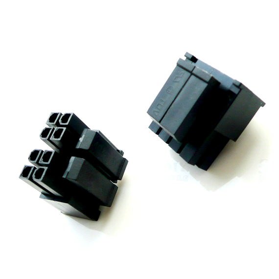
8 Pin PCI Express (PCIe) Power Cable Connector
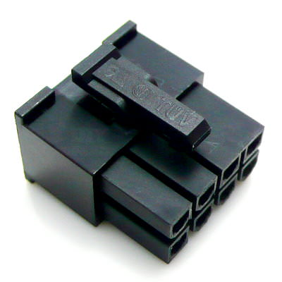

The PCI Express 2.0 specification released in January 2007 added an 8 pin PCI Express power cable. It's just an 8 pin version of the 6 Pin PCI Express power cable. Both are primarily used to provide supplemental power to video cards. The older 6 pin version officially provides a maximum of 75 watts (although unofficially it can usually provide much more) whereas the new 8 pin version provides a maximum of 150 watts. It is very easy to confuse the 8 pin version with the very similar-looking EPS 8 pin 12 volt cable.
The 8 pin PCI Express and the EPS 8 pin 12 volt connectors are polarized differently so you won't be able to plug one kind of cable into the other kind of connector. That is, you won't be able to plug the wrong kind of cable in unless you try really hard. Unfortunately, the Molex Mini-fit Jr. connectors used by both kinds of power cables can sometimes be forced into a differently-polarized connector if they only have a few pins and you push hard enough. If the cable won't slide in easily then you're probably trying to insert the wrong kind of cable. The 8 pin PCI Express connector does have a small plastic bridge which prevents it from being plugged into an EPS 8 pin 12 volt motherboard connector. You can see the bridge in the image above between the rightmost two pins in the top row of the connector. But there's no such protection to prevent EPS 8 pin 12 volt cables from being plugged into an 8 pin PCI Express connector on a video card. That combination may fit if you shove hard enough. And if you plug in the wrong kind of cable then expect fireworks. Some of the grounds and 12 volts wires for an EPS 8 pin 12 volt are reversed compared to an 8 pin PCI Express. Fortunately, most 8 pin PCI Express connectors are labeled "PCI-E" so people won't confuse them with EPS 8 pin 12 volt cables. If the connectors aren't labeled then you can tell an 8 pin PCI Express power cable from an EPS 8 pin 12 volt cable by checking the color of the wires which plug into the clip side of the connector. On the EPS 8 pin cable, the yellow wires (the 12 volt wires) go into the clip side of the connector. On the 8 pin PCI Express cable, the wires on the clip side are all black (grounds). That's the same as it is with the 6 Pin PCI Express power cable. Of course, none of this helps you if your cable uses the trendy all-the-same-color-wires design which is popular with high-fashion power supplies. In that case you'll just have to be very careful or hope the connectors are labeled.
| Pinout | |||||
|---|---|---|---|---|---|
| Pins 1 through 3 | Pins 4 through 6 | ||||
| Description | Wire color | Pin number | Pin number | Wire color | Description |
| +12 volts | yellow | 1 | 5 | black | ground |
| +12 volts | yellow | 2 | 6 | black | ground |
| +12 volts | yellow | 3 | 7 | black | ground |
| ground | black | 4 | 8 | black | ground |
| Official cable/connector maximum wattage delivery | |||
|---|---|---|---|
| Voltage rail | Number of lines | Maximum current | Maximum wattage |
| +12 volts | 3 | 4.167 | 150 watts |
6+2 Pin PCI Express (PCIe) Power Cable Connector
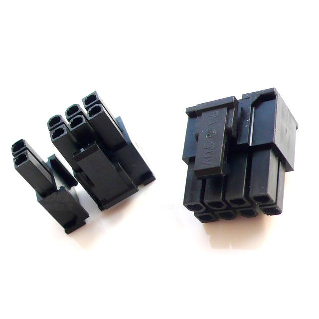
Some video cards have 6 Pin PCI Express power connectors and others have 8 Pin PCI Express power connectors. Many power supplies come with a 6+2 PCI Express power cable which is compatible with both kinds of video cards. The 6+2 PCI Express power cable is made up of two pieces: a 6 pin piece, and a 2 pin piece. If you put the two pieces together then you have a full 8 pin PCI Express power cable. But if you split the connector into two parts then you can plug the 6 pin part into the older 6 pin PCI Express connector and leave the 2 pin part unplugged. That way, your power supply only needs to have one 6+2 cable to be compatible with both 6 pin and 8 pin PCI Express connectors.
4 Pin Peripheral Power Cable Connector
The four pin peripheral power cable dates back to the original PC. It was used for floppy drives and hard disks. It's still around and is now also used for all kinds of things including add-on fans, extra video card power, supplemental motherboard power, and case lighting. It's as old as the hills but is still very widely used. The connector is shaped so that it only fits in one way. You don't have to worry about inserting it the wrong way. People often use the term "4 pin Molex power cable" or "4 pin Molex" to refer to a four pin peripheral power cable. It's not a technically useful term because the 4 pin 12 volt cable is also a 4 pin Molex cable (Molex makes lots of connectors) but "4 pin Molex" is commonly used to refer to peripheral cables anyway.
| Pinout | ||
|---|---|---|
| Pin number | Wire color | Description |
| 1 | yellow | +12 volts |
| 2 | black | ground |
| 3 | black | ground |
| 4 | red | +5 volts |
| Connector part numbers | ||||
|---|---|---|---|---|
| Socket housing | Socket | Pin housing | Pin | Maximum current per circuit |
| AMP 1-480424-0 | AMP 60619-1 | AMP 1-480426-0 | AMP 60620-1 | 13 amps |
I don't know of any official definition of the maximum current allowed in a peripheral cable. The connector can handle 13 amps according to the manufacturer. But you normally find 18 awg wire in the peripheral cables. If you have an 18 inch cable (about a half a meter) and are running 13 amps through 18 gauge wire then you get a voltage drop of about 0.25 volts counting both the power wire and the ground (it's got to go both ways) and the dissipation is about 3.3 watts. That's not good. I've just played it safe and listed the maximum current as 5 amps.
| Unofficial cable/connector maximum wattage delivery | |||
|---|---|---|---|
| Voltage rail | Number of lines | Maximum current | Maximum wattage |
| +5 volts | 1 | 5 amps | 25 watts |
| +12 volts | 1 | 5 amps | 60 watts |
Current power supplies usually have at least two separate peripheral power cables, each of which has two or more peripheral connectors. When you're plugging in multiple high powered devices it's a good idea to spread the load between all of your cables. Don't just plug all your devices into one cable unless they're relatively low load devices. Spreading the current between the cables reduces the voltage drops and power loss. If they're relatively low current devices like fans or it's just a disk drive or two then it doesn't really matter. But if you're putting lots of hard disks into a computer (some can draw almost 3 amps at 12 volts when doing some operations) or connecting a video card's auxiliary power, then spread the loads between the peripheral power cables. It's also helpful if you use a connector as close to the PSU as possible rather than sticking things at the end of the cable. Extra wire just means more voltage drop. And if you're using a peripheral connector to PCI Express adapter then be sure to plug each of the adapter's peripheral connectors into a separate PSU cable. They gave you two peripheral connectors for a reason. Plugging them both into the same PSU cable forces your video card to draw its 12 volt power through one 18 gauge wire. That increases your voltage drop and power dissipation in the cable. Some current high-end video cards can suck up more than 10 amps at 12 volts with most of it coming through the PCI Express connector so it pays to be careful. It will probably work if you don't spread the load but there's no excuse for not doing it properly. They gave you multiple cables. You might as well use them. Plus there's just something creepy about having warm wires even if they're not melting.
You will occasionally run into peripheral connectors which don't have all four wires. They are usually 12 volt only cables intended for fans. Never plug one of those into a disk drive. Drives expect both 5 and 12 volts to be provided. Some of the two-wire peripheral connectors are for speed-controlled fans. That means that the voltage changes depending on the desired fan speed. The connector will only provide 12 volts when the fan is going full speed and the voltage decreases to slow the fan down. Definitely don't plug that one into anything but a fan! Normally this kind of peripheral connector has "fan" printed on it to warn you. As long as a peripheral connector has four wires: one yellow, two black, and one red and it doesn't have some kind of printed warning attached then it's a standard peripheral cable and you can plug it into anything.
SATA Power Cable Connector

SATA was introduced to upgrade the ATA interface (also called IDE) to a more advanced design. SATA includes both a data cable and a power cable. The power cable replaces the old 4 pin peripheral cable and adds support for 3.3 volts (if fully implemented). The connector is shaped so it can only be plugged in the correct way.
| Pinout | |||||
|---|---|---|---|---|---|
| Pin number | Wire number | Wire color | Description | ||
| 1 | 5 | orange | +3.3 volts | ||
| 2 | 5 | orange | +3.3 volts | ||
| 3 | 5 | orange | +3.3 volts | ||
| 4 | 4 | black | ground | ||
| 5 | 4 | black | ground | ||
| 6 | 4 | black | ground | ||
| 7 | 3 | red | +5 volts | ||
| 8 | 3 | red | +5 volts | ||
| 9 | 3 | red | +5 volts | ||
| 10 | 2 | black | ground | ||
| 11 | 2 | black | ground | ||
| 12 | 2 | black | ground | ||
| 13 | 1 | yellow | +12 volts | ||
| 14 | 1 | yellow | +12 volts | ||
| 15 | 1 | yellow | +12 volts | ||
| Connector part numbers | |||
|---|---|---|---|
| Cable connector | Terminals | Maximum current per circuit | |
| Molex 67582-0000 | Molex 67581-0000 | 1.5 amps | |
| Official cable/connector maximum wattage delivery | |||
|---|---|---|---|
| Voltage rail | Number of lines | Maximum current | Maximum wattage |
| +3.3 volts | 3 | 4.5 amps | 14.85 watts |
| +5 volts | 3 | 4.5 amps | 22.5 watts |
| +12 volts | 3 | 4.5 amps | 54 watts |
You have to be careful about SATA power cables. Some of them are missing the 3.3 volt wire. People with older power supplies often use adapters which convert from 4 pin peripheral cables to SATA power cables. But since 4 pin peripheral connectors only supply 5 and 12 volts, the SATA connector is missing 3.3 volts (there's no orange wire). There are also a few older power supplies which inexplicably have SATA power cables which are missing the 3.3 volt wire. Currently, SATA drives rarely use 3.3 volts. That may be because there are too many people using adapters so the drive makers don't want the headaches which come with using 3.3 volts. But in the future, 3.3 volt drives may become common so you need to be careful when using SATA power cables which don't implement 3.3 volts.